As explained in my introduction to Pilot Wave Hydrodynamics (PWH), the model is just a shaking bath of oil. So, we build a machine to shake a dish of oil. In my case it is a speaker on top of some wood posts that I can feed sine waves from my iPhone. This is much in line with other experiments in PWH, at least the lower-cost ones. Of course, one could spend as much as they want to get industry-grade shakers that simulate earthquakes and whatnot, but my simple shaker is more than enough to test some of the phenomena.
I built my shaker using mostly parts I had at home. While it is for research at the university, it started as a project I did first for a physics competition, and later for fun. Four pine posts were cut from some scrap I had lying around on my bandsaw, and I cut slots in the lower part of them to hold a plywood shelf. This shelf both holds the posts together and the amplifier circuit that runs the speaker. On the top of posts, I screwed in the speaker. This, while not as professional as I had hoped, does give me some leeway in leveling out the speakers, by tightening the screws fully or leaving them a few millimeters above the posts.
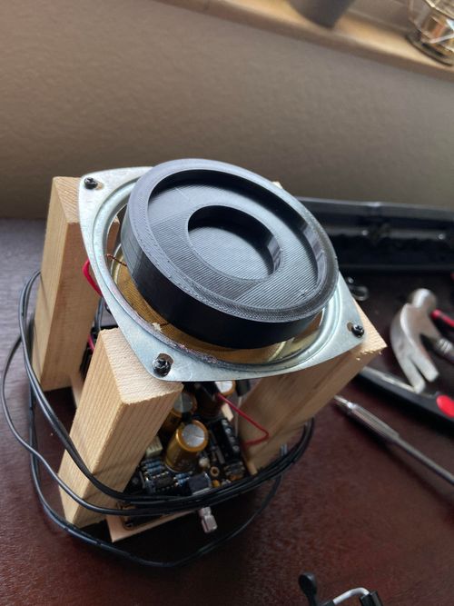
For the experiments I wanted to run, I needed a way to make different shaped dishes, with a certain topology layout of deep and shallow oil. That lets us make corrals that trap droplets, narrow channels for them to pass through, etc. Starting this mission, I had to design a low force, yet sturdy connection. We have to connect our dishes to a thin metal cylinder that houses the coil in the speaker. I figured I could use the slight bend that thin plastic allows to make a tight fit.
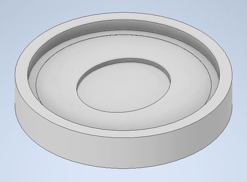
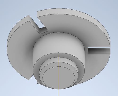
After some CADing, I got the following models worked up. Since 3D printing is limited in how it makes overhangs, and I didn't want to waste time with supports, so I made the interchangeable dishes two parts. One is the dish itself, with 3 insert holes on the bottom. Then I have the twist collar with 3 posts. This also allowed for easier prototyping, as I could hone the twist part independently of the dishes. On the speaker is also a disk with three slots to mount the dishes on.
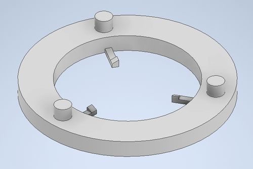
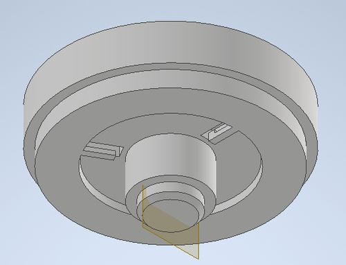
When the base and dish assembly are rotated relative to each other, the triangles on the twist base fingers act like ramps, that allow counterclockwise rotation but not clockwise rotation of the dish. When the dish is turned counterclockwise, a spring force is generated by the deflection of the fingers that holds the dish on tight, while a clockwise rotation will go until the fingers hit the side of the slots in the speaker adapter, making it easy to remove without seeing the underside of the dish.
All in all, I'm impressed with how well this project turned out! This was my first project with my new 3D printer, and I missed how quickly the prototyping process was. In fact, I have a picture that shows well just how many different measurements I tried.
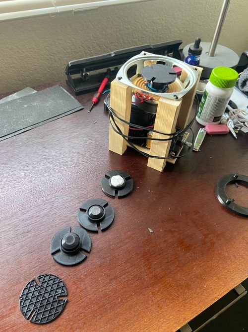
I'm impressed with how well it came together. To deal with some tolerance inconsistancies with 3D printers I place a few pieces of electrical tape on the bottom of the dish. While each print I keep tweaking the numbers a bit to try and get a better fit, this lets me have a well fitting part regardless of how my printer is feeling day to day.
leviticusrhoden.com Homepage Back to PWH Research RSS Feed Send Me an E-Mail!