So, why a thin lens simulator, first of all? Lets start with the simulation part of it. I wan't to make a camera lens assembly (don't worry, we will talk about that project at a diffrent time on a diffrent page), and have learned optical simulation programs can cost $100's of dollars. Quite frankly, those programs also annoy me because they never work how I want them too. So, to save money and have control over everything, I decided to program my own! As for the thin lens part, that is an unfortunate consequence of buying lenses form a surplus store. While the lenses are a tenth or less the price of new lenses, they do end up lacking some of the finner meassurments. No worries, I happen to not be a stickler on aberations and such. So while the math of this simulation would be the same for a thick lens (I think), the boundry detection is much easier and wolud need a revamp to accommodate curved interfaces.
Alright, with the motivation defined, what is the nitty gritty of what I want it to do? Basically, I've got a list of ~20 lenses that I think could work, and I want to see if any combination of them (and gaps between them) yield a good lens assembly. This "good lens" definition is mainly defined by where and at what scale images are formed. Think how and where would I have to put film to have an in focus image from this lens. The best end product could run through all kinds of diffrent lenses, find where the light rays intersect, record that, and then present to me all of the lens assemblies with their image location and scale. An important note here is that it is not up to the program to pick The Best lens, simply show me some of the best so I can make a decision and tweak that design.
One last note, I will use the word "lens" to refer to a single piece of glass with optical properties, and "lens assembly" to refer to one or (usually) more lenses with the express purpose of focusing light onto a sensor or piece of film.
If you ever took a high school or college physics course, you might remember a ray trace like the one below.
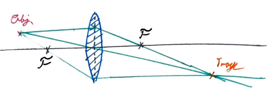
These guys are wild. And not to mention, anoying to solve. What we are told here is that we can draw the top trace parallel to the opical axis, or horizontal, and that means when it hits the lens it goes through the focal point. Then we draw a line from the object to the center of the lens, meaning it does not change course and keeps going straight. Then for good meassure, draw the line through the object and the left side focal length till it hits the lens, then it comes out parallel to the optical axis. Where the three lines intersect is the image! So obvious! And if you said you wanted a smattering of analytics, you'd get a neutered Lens Makers equation like so.
If you couldn't follow that, please don't worry. Neither could I. It is an ad hoc method for getting an intuition for lenses, but does not really help us in this case. I want to make individual rays, and wether or not they are one of the above three plot its path through the lens assembly. So I did what any sane man would do, I tried to see if there was a way to rearange variables to make more sense of the math. And I came up with something I am quite proud of! Now, I'm sure it's already exsisting out there, and I may have heard it in passing at one point, but as far as I can remember, this is a novel idea? It was never taught in class, so I think I can claim I formulated this independently. If anyone has seen this before, please let me know where from! I'd love to read up a more formalized, and probably more correct version of this!
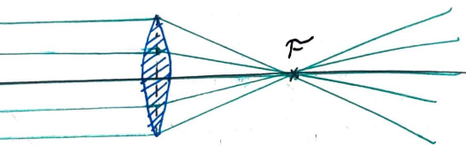
We start by thinking about what focal length is. It is where parallel light rays are focused with a lens.
Focal distance is in units of length, specifically mm. Now, if you happen to be taking an electronics class at the moment, you might remember how it is sometimes easier to do math with 1/x, instead of the variable x. Lets do that with focal length and get
where c is inverse focal length. Now, c has units of 1/mm, or per mm. This is starting to sound like a slope! So, if we have a parallel light ray hit the lens at a height 1mm from the optical axis like so,
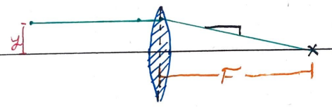
and we end up with a light ray with slope c! Look back at the focal distance image and notice the farther the incident (incoming) ray was from the optical axis, the steeper it's slope is. For a parallel ray, this slope is whatever is needed to get from it's height when it hits the lens to the focal point. Let's define this height as y. So, when a horizontal ray (ie, it has a slope of zero) hits a thin lens, its slope exiting the lens is
Now that we have a mathematical framework for horizontal in light rays, lets see if we can't generalize it.
So we saw above that light rays with zero slope exit a lens with a slope of yc, where c is the Rate of Convergance, or inverse focal length of the lens, and y is distance from the optical axis (where y=0) that the incident ray hits the lens. To explore how these slopes compound, lets look at the example of an object that is a focal distance away from the lens like such.
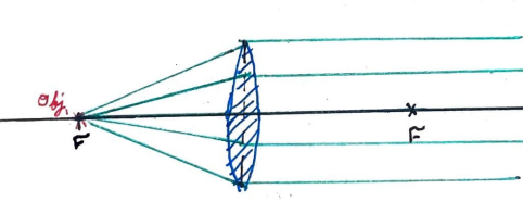
Here, our lenses start with a slope, and then some sort of transformation or compounding of it's slope happens, and it leaves the lens with no slope. We know the origonal slope of any ray from the object is yc, as the rise is the eventual y of the ray when it hits the lens, and the run is focal length. And we see that the lens itself modifies this slope in some way by, with it's input slope of yc.
To put this more clearly, we imagine the lens as a machine that modifieys a light rays slope, as some sort of function of the yc of the lens and the slope of the incident ray min, to return to us the slope of an outgoing ray mout, or
So looking at the object at the focal length, we can say min is equal to yc, so what can our fuction L(yc,min) do to get us zero? Using simply intuition, we can hypothosize our function looks like this.
The easiest way to test this method may be to see if it agrees with the lensmakers equation shown above,
This is as easy as drawing the following lens diagram and labeling it's parts.
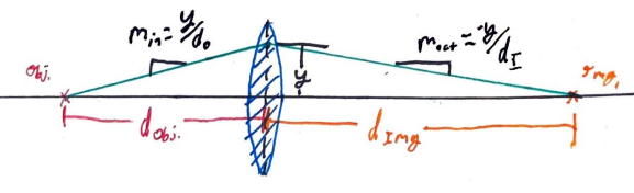
Looking at this diagram, we can find a simple equation for min and mout, using that good ol' rise over run stuff from middle school.
.Now we make the wild assumption that my theory for the L function is correct.
So, pluging in these functions for min and mout into our ray transform function L, we get
,which can be reorginized into a very familiar form,
.I hope this breakdown is elementry enough to be noticed as the lens maker's equation, as y can be factored out of both sides. While not rigorus, I hope this should at least convince you that this is not a dumb idea. Plus, I'm an engineer. Theory proves itself not by being mathematically sound, but by getting me results that work in the real world! How'd that soap box get here...
The principle mathematics of my simulation is based off of two mathematical assumptions:
My code can be found on my github, linked below. The main file you'll want to look at, assuming you want to look at the code, is lenses.py, which is a module with all of the functions and the lens system class I made. I did my best to put in comments and docstrings, so hopefully looking through that will give you an idea how it works. All the other code should give you ideas how to use it.
This repository should be kept up to date with my work on this. As it stands, I don't plan on releasing a polished easy to use version, as I have it setup for my needs already. However, I've got a few sub functions in this code I think one could find useful.